

RUFE Platform
ASSP development platform for industrial equipment with Intel MAX 10 FPGA

RUFE is an Evaluation platform for development of our own ASSP and measures
- MAX10 10M08SA mounted: 3.3V available with single power supply and built in configuration ROM that operates on single chip.
- Dial Boot compatible, Nios II can also be installed.
- MAX10 analog feature can also be used to perform power sequence and management of the board.
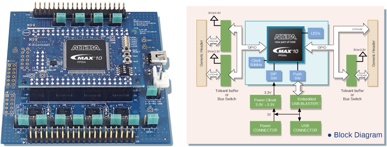

Characteristics of the baseboard combination
- USB BlasterⅡ Mounted
・Can develop without having a FPGA writing machine.
・Can operate FPGA in GUI using system console.
・SignalTAP II can also be used as a Rosiana. - Drive Buffer TypeA
The 5 V system is equipped with a 3.3V-5V tolerant buffer for applications requiring drive capability - Drive Buffer TypeB
It is equipped with an FET switch type 3.3V-5V tolerant function that does not require DIR/OE control.
Specifications
| Core specifications | ||
|---|---|---|
| FPGA | MAX10 series | 10M08SAE144C8GES |
| Power | 3.3V single | Supplied from baseboard |
| Clock | 50MHz | 1 unit installed |
| GPIO | 2.54 2 x 20 x 2 row connectors | |
| Connector | Enlarged A1 - 40 PA - 2.5 DSA (Hirose Electric) | |
| Each connector 36CH | Total 72CH | |
| ADC | Connector | Unimplemented |
| Dedicated input 1CH | Shorted to AGND with 0Ω resistor | |
| GPIO shared port 8CH | ||
| AVREF | Supplied from connector | |
| LED | POWER LED | 1 unit installed |
| USER LED | 5 units installed | |
| DIP switch | For 4 consecutive 1 UNIT Installed | 3 general purpose points |
| 1 point 1 Configuration SEL dual (also included in GPIO connector) | ||
| Push switch | 3 UNIT Installed | Reset switch * 1 |
| General purpose (also installed in nConfig pin GPIO connector) | ||
| General purpose (also installed in nStatus pin GPIO connector) | ||
| JTAG | Connector | 1 unit installed |
| USB Blaster II can not be used when connecting to baseboard. It is possible to write using the USB Blaster II with the core board alone. (A separate 3.3V supply is required.) |
||
| * 1 It can be used as a general purpose. | ||
| Base specifications | ||
|---|---|---|
| Power | 5V single | |
| Supplied from USB connector or power connector (selected by jumper) | ||
| 3.3V power supply for FPGA installed | ||
| GPIO | 2.54 2 x 20 x 2 row connectors | |
| Connector | Enlarge A1 - 40 PA - 2.5 DSA (Hirose Electric) | |
| CN9 | Buffered GPIO 32CH (4, 8-bit buffers) | |
| Unbuffered GPIO 4CH (Direct FPGA connection) * 1 | ||
| Total 36CH | ||
| CN10 | Buffered GPIO 16CH (2, 8-bit buffers) | |
| Unbuffered GPIO 20CH (Direct FPGA connection) * 1 | ||
| Total 36CH | ||
| GPIO buffer A * 3 | 3.3V/5V tolerant buffer | |
| Buffer IC | Equipped with SN74LVC8T245PW x 6 | |
| Drive voltage selection | Individually configurable for each 8CH (5V/3.3V) | |
| OE | Fixed setting/control setting possible * 1 | |
| GPIO buffer A * 3 | 3.3V/5V tolerant buffer bus switch | |
| Buffer bus switch | SN74CB3T3245PW x 6 個 搭載 | |
| Drive voltage selection | 3.3V fixed | |
| OE | Fixed setting / control setting possible * 1 | |
| LED | POWER LED | |
| Programmer | Micro USB connector | |
| Embedded USB Blaster installed * 2 | ||
| * 1 One GPIO is assigned to the control function. * 2 Cannot be used as a USB BLASTER II with a base board alone. * 3 Buffer type is selected as either one or the other. |
||